Search This Blog

Tuesday, October 15, 2013

Bridgeport Update DRO

So I have a Bridgeport milling machine, it was made in 1941 making it 73 years old.  The table show abuse, but its flat within .001 across the 42 inch surface.  The spindle runout is less than .001 I only have an indicator that reads in thousandths. Still need to adjust the gibs and adjust the acme nuts to get the backlash down.

The only bad thing for me is that it is missing alot of parts for the spindle auto feed, and it will be expensive to fix but a necessity.

So I ordered a DroPros DRO system 2 weeks ago and finished installing it last week, Ive played with it a little but havent made many chips yet.  I also ordered a Kurt Vise on ebay, nut Kurt Style but an authentic Kurt.

Ive done one thing with the mill so far that was a first for me, but sadly I have no pictures.  My brother had a moped cylinder head that needed to be shaved, he asked me to take .020 off the top, so I did.  He put it back on the moped, and all seams to be good.


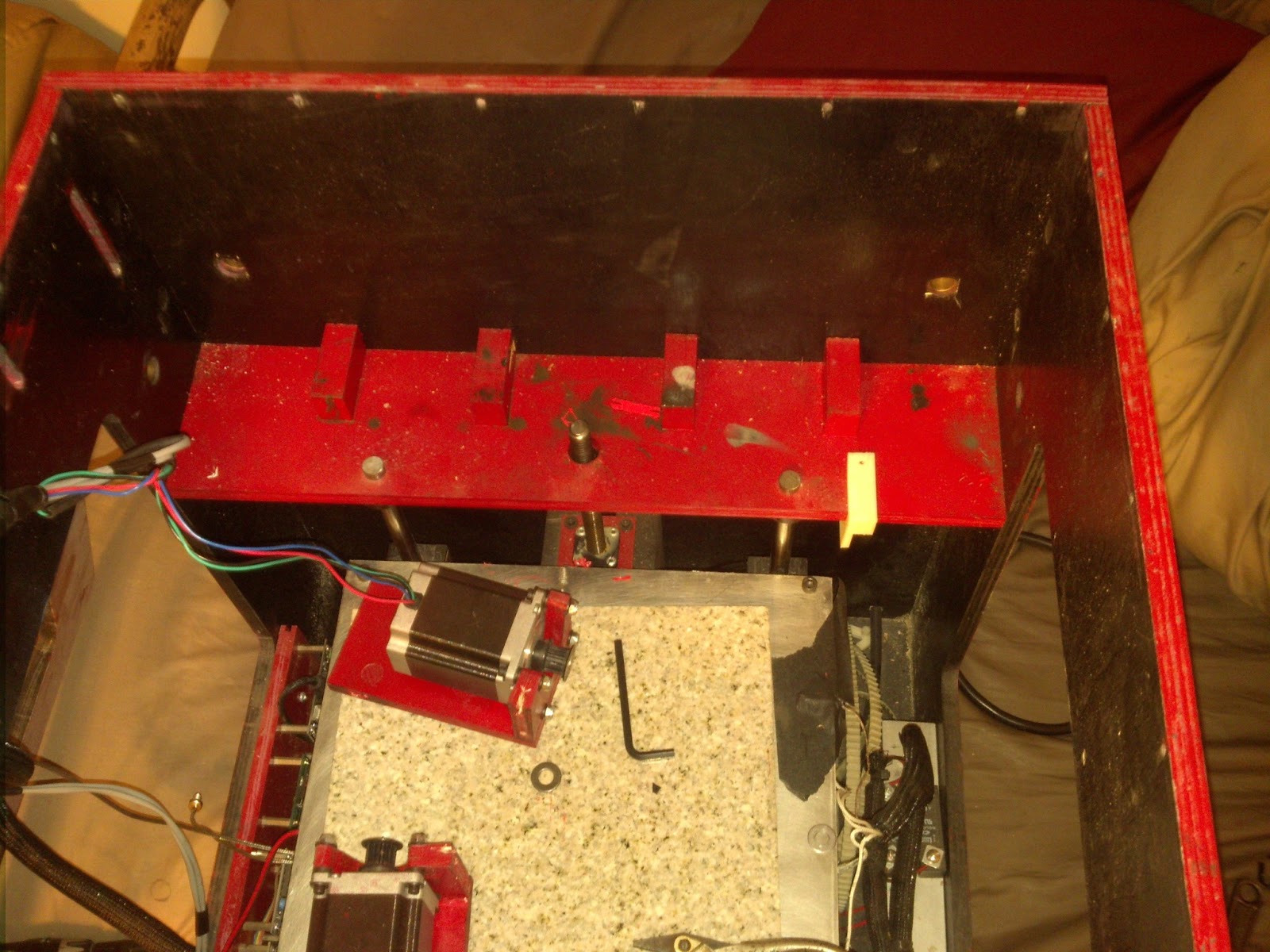
Now for a picture, the following picture is before the Z axis slide was installed and before the wires were tidied up.

Wednesday, September 25, 2013

New Tool!

So just recently I picked up a new tool for incredibly cheap.  The tool is a Bridgeport mill manufactured in 1941.  The mill itself is in decent shape and is missing a few parts, but is semi functional as is.  I purchased this mill from a friend (I didnt even know he had it) and was told it came off of the USS North Carolina Battleship.  I do not know if thats true it just makes it that much more awesome.

Here is a picture of the machine as it sat before any cleaning/work, but in my garage.

Once I make some repairs and clean her up there is a good chance I will post more pictures.

Tuesday, August 27, 2013

Overhang Tip

So last night I finally finished reassembling my printer.  Im not satisfied with some changes, and they will be changed again but that is for another post.

So for my printers first of many first prints I decided to print the Colassal Bust of Ramesses.  The new cooling setup has reduced curling completely.  But when the print was nearing his "beard" I didnt want the printer to print in mid air.

So here is what I did: I folded a piece of painters tape in half, I then stuck it to the part where the support was needed with the seem at the current printing location.  Pictures below.


As you can see for this small simple overhang a piece of masking tape added all of the support needed.

The print is not finished, as it was getting late, so I paused the print, and shut the printer off.  Im hoping that when I restart the printer and resume the print it will resume correctly.  I will update on the results.

Tuesday, July 30, 2013

Link Sharing

Past couple of weeks i've seen a couple of links that others may like to know about, or may already know about.

MIDI to Gcode web app:  http://en.homeconstructor.de/converter-convert-music-in-g-code.html
This link takes you to a web app that converts your MIDI files into gcode, and in my opinion is a lot easier to use than the python program that does the same (mainly because i cant get the python one to work.)

Monoprice.com sells 3d printer filament! http://www.monoprice.com/products/subdepartment.asp?c_id=107&cp_id=10724
3 colors in 3mm and 1.75mm.  They do not mention the tolerances of the filament though.  Has anyone tried this?

These two links may be old news to some, but some may find them new and useful.

Sunday, July 14, 2013

Reassembly


New extruder carriage with Lulzbot Budaschnozzle.

Old parts, cast extruder carriage, and wooden X and Y carriages.

Disassembly.

Reassembly, no belts installed at this point.  Also the X and Y carriages are just slightly to long, Im hoping a quick trip to the belt sander will fix that issue.

At this time I have the belts installed. I still have to sand a little from the rear carriage, tighten up the set screws on the pulleys.

After a little more time I will run some gcode without the extruder hooked up just to break in the bearings.

Monday, July 8, 2013

XY Changes Incoming

Recently I have been experimenting with higher speed prints, currently I can print reliably around 50-65 mm/s and travel at 125 mm/s.  I want to double that for quick prints, maybe more than double it.  Currently I am running linear ball bearings on the extruder carriage, and brass bushings on the X and Y carriages.

I have designed and printed all new parts for all moving parts, I have also moved to 12mm aluminum linear rod for the moving rods.  The X and Y carriages will be using freon lined linear bearings (I had them) and the  extruder carriage will be using Igus J-glide plastic bearings.  All ball bearings are out of the question due to weight.  Eventually I will upgrade the X and Y carriages to Igus J-Glide as well.

The current carriage with extruder weighs in excess of a pound, counting all other moving parts on the XY cartesian system is probably close to 4 pounds, its heavy.

The new printed carriages and aluminum linear rods should bring me to around a pound.

The only part keeping me from assembly is the tubing connector to attach my Bowden extruder up to it.  Assembly should happen within the next week.

Now for some 3d shots taken from Inventor, and a picture of the printed components.

The X and Y carriages in this pic have stainless 1/4-20 SHCS, when I make my next McMaster order they will be replaced with Nylon set screws.  Also the PLA itself was carefully tapped for the threads, I believe I used 4 perimeters on these.


Friday, June 21, 2013

My printer is almost to where I would like it to be, I have some potential firmware issues that I hope to get rid of by upgrading to new hardware that is actively being supported.

Most recently I designed a phone case for my Motorola Razr because I was getting bored with my current case.

The fit is perfect, and the build quality is ok.  I have shared this file on Thingiverse as well: http://www.thingiverse.com/thing:1071440

I'm currently revising the cartesian system to lose weight from all the moving parts.  Currently i'm printing at 80-100 mm/s with travel moves at 135 mm/s Id like to push 150/200 mm/s respectively.

Ill try to update again soon, Thanks for visiting.

-Jeff

Tuesday, December 11, 2012

Problem, Prints lean to one side, Fixed

So there is this problem that effected my first printer the Boxed Reprap I called it, the problem was that prints would lean in one direction, always the same direction.  This printer was very large and used the gen 3 electronics from makerbot.  Solution is at bottom.

With help from every one that would volunteer help in the opensource 3D printer world I checked many many different possibilities:
Stepper drivers: I swapped them around, still leaning
Steppers: swapped them around, still leaning
Checked for binding, axes would move very smoothly in any direction
Z axis was vertical

I could not get this printer in the end to print perfectly vertical it was missing or skipping steps, I eventually assumed it was from the print bed being so heavy, since it started when I went to a moving bed setup, and it was such a large bed.

So came Artifex, my current printer Designed in cad to keep friction and weight down made the printer significantly smaller, kept the same build area, and reused almost all of the mechanics except for the ball screws.  This printer is built with the Ultimaker as inspiration.

Prints still leaned, the printer had all new electronics, different bearings different mechanics I didnt understand, even the steppers where different and new.  So I had to continue to troubleshoot.

After doing all of the same troubleshooting again I came upon the cause by accident, it was the computer.  The more cpu intensive work I was doing on the computer while printing, the more the part would lean, stop doing pc work and it would lean less.

Solution: So I printed from SD card, prints leaned less, then I printed from SD card and unplugged from the computer, leaning was gone!

There was so many more things that I tried, but I was so mad at myself for not figuring it out sooner, but without mistakes we will never learn.

Monday, December 10, 2012

Artifex

Not many updates recently, but I will post a picture of Artifex, the printer I built last year.Artifex works remarkably well, it is based of of the Ultimaker design. It uses linear sliding bearings in the guide blocks closest to the frame and linear bearings on the extruder carriage.

The problem that I had with Artifex was getting the holes in the extruder carriage perfect for sliding bearings before I decided to go with linear bearings.

specs:
 .9 degree nema 23 steppers around 2 thou per step at 8X micro-stepping
gen 4 electronics without the extruder controller
heated bed
 PID control for extruder and bead
acme screw z axis
MK7 Hotend

In the coming days I will post about my projects from last year. I hope to start working on my printer again soon.

Future Posts include: Pictures of a few prints, an interesting problem that caused prints to print crooked with no obvious pattern, making an extruder carriage out of urethane resin, maybe a clip of my printer doing the imperial march, and I may even include some pictures of my non printer project the "Skate-Cart" a gocart skateboard combination death trap of a device. I was even working on a Semi easy 1.75mm to 3mm swap for the MK7, only because I have some 3mm plastic left.

Well thanks for reading and enjoy!


Friday, December 23, 2011

Not 3D printing, Freddy Kruger glove

I have been working on lots of small projects recently, this one I started a few years ago, by making one finger. Recently I decided to work on it a little more so I made the other 3 fingers the blades and the top hand piece. Everything but the blades are made of copper, the blades are made of aluminum. All parts are riveted together and the blades are brazed on. How the glove sits now is probably how it will sit for awhile. Picture:

Monday, October 17, 2011

Monstrous Powerful Large Ultimakerish Clone

It has been awhile since I have made any updates, I have been working on my printer with a moving bed design, and not liking it. So I have decided to go back to a moving extruder, but this time unlike my last moving extruder design im going to imitate the Ultimaker style XY and makerbot/ultimaker style z axis.

First 2 pics of the mockup in Autodesk inventor:

Photobucket
Photobucket


The first thing you may notice is the all wood construction, the box will be constructed from rough oak milled and jointed to my specifications. You may also notice the box joints, these serve to purposes one strength and two cosmetic. This printer will be built to perform and to look stunning.

You may also notice that all mounts for the steppers, rods, idlers are all integrated into the framework of the printer, this is for simplicity of parts and again I believe it will help with strength.

Only 4 printed parts, they are the moving XY rod carriers.
I still need to do alot of final touches like add fasteners and check for interferences, but if it all checks out I will start construction towards the end of this month early next month. Just need to borrow some wood working tools from my dad.

Stats:
Steppers XY axis 2 motors Nema23 .9 degree step 260+ oz-in, Z axis 1 motor Nema 23 400+ oz in
Electronics Makerbot gen 4 with X8 micro stepping
1/2" linear bearings
4 linear bearing rods on Z axis
1/2-10 acme lead screw on Z axis
MK7 Hot end
Heated bed from last printer
12" x 12" x 16" build area or for yall across the pond 304.8mm x 304.8mm x 406.4mm

Monday, May 30, 2011

Custom .25mm MK5 nozzle and Monitor Mount

I wanted a way to mount the monitor and be able to move it out of the way. What I decided to do is add drawer slides rated for 100lbs to the inside of the printer box on the slide is a hinged arm that the monitor and its electronics are mounted too. Its easiest to explain by showing pictures:


Photobucket
Photobucket
Photobucket
Photobucket
Photobucket
Photobucket
Photobucket
Photobucket
Photobucket
Photobucket


I also got the extruder up and going with my MK5 style nozzle with a .25mm orifice, the extruded ABS measured .30mm in diameter, the test was completed at 450 degrees F. If there is interest I may make a tutorial on how to make the nozzles or make a few and post them on eBay for sale. They are made of brass unlike the Makerbot stainless nozzles.

Sunday, May 29, 2011

Z Axis Success and Starwars

A few days ago I received my timing belts for the Z axis and the 115 tooth belt was a perfect fit. After installing the belt I noticed that my alignment was off enough that the belt could come off the pulley, so I made a "flange." The flange, which you will see in a video posted below, also doubles as a Z axis adjustment knob.

As I did with the XY axis I added a substantial amount of weight to the z axis probably about 10 pounds to test the movement. In RepG it would jog at about 400 mm/min with out the axis being calibrated. It takes about a min for it to move through its 12ish inches of movement.

My new thermocouples came in, they are way to long but that was purposely done. The bed PID controller was bad, so I ordered a slightly better new one for the extruder and the old extruder one will be used on the bed.

I received some electronics from China that make it possible to use an old laptop monitor as a computer monitor using VGA or DVI.
Link: LCD Controller Board Kit with DVI Interface
It works flawlessly. I am now working on a over built monitor stand that includes drawer slides and cabinet hinges and the hinges from the laptop.

Tomorrow I plan on attaching the thermocouple to the hot end, calibrating the XYZ axis, and test the extruder to make sure that my nozzle works properly.

The video is of the printer playing the well known "Imperial March" gcode from the makerbot website.

Wednesday, May 25, 2011

XY axis Test

In the last post I mentioned that I had tested the movement of the XY axis, I have finally gotten around to uploading it to YouTube. It will be posted bellow.

XY axis information:
build area: 11"x11"
Build plate: 12"X12"
Steppers: Nema 23 160 oz-in if I recall, 3 in total for XY
belts/pulleys: 11 tooth plastic commercial pulleys .2" pitch
Linear Motion: Thompson Linear bearings on 1/2" shaft

After filming this video I decided to raise the Z axis and put a 10lb back of grout on top of the build axis to see if it seamed to loose steps or stop working. It remained working like that for the remainder of the 20min print. Afterwards I used rep z to do the maximum length jog at 4000mm/min and even with the excessive weight it preformed perfectly!

any other questions just ask.


I decided to measure the Z axis for the proper belt and I ordered 2 belts 115 and 119 tooth belts both 3mm pitch. Im hoping I can get the 115 tooth belt to work without a tensioner, if not I will use the 119 with a tensioner.

Right now I am hoping that the z axis will perform just as well as the XY axis. The z axis has always been the hardest part for me. I still need to work on some adjustments on it though.

Sunday, May 22, 2011

Update

All of the electronics are now finished, 90% of wiring is completed, all wires are ran. Thermocouples are harder to extend than anticipated, so I ordered new ones at the proper length, 1 5m length and 1 3m length id rather them be longer than shorter.

The computer is up and going windows 7 ultimate 64 bit with all the needed software installed, RepG, Skeinforge, Python, Arduino, ect. Debating if I want to install Inventor on that computer as well. This printer is meant to be completely self contained, It will be possible to do everything from the printer: R&D, design, and manufacture.

Ran a 20 min dry run with the xy axis to see how well everything works, 1/8 micro stepping is 10X quieter than before with full steps, before I also had a bunch of rattles that has been fixed now.

Things left to do:
secondary belt splice for z axis
wire up thermocouples
solder up bed heater
retune/setup PID controllers
Add Z axis stop
Add/wire for fans on all stepper motors plus pin point fan for build surface
devise a monitor mounting solution that fits the printer well
mount keyboard and mouse in an adequate place
figure out why the left Y axis motor isnt working, wiring? driver? settings?
probably a few things I left off


The XY build platform has some flex to it, I believe it will be fine for printing, but im not satisfied with it. 90% of the flex is forward to backward due to the spacing of the two linear bearings, I plan to fix that in a future revision. But when looking at the parts that are flexing a lot of the flex is coming from my linear bearing rods. The rods are 1/2 diameter 22" long steel of some sort, they came with the bearings when I ordered them second hand. I may order 2 new linear bearing rods from Mcmaster to see if it helps with my problem.

I hope to be printing by the end of May or the first week of June, I really want to print a florescent green green lantern ring for the green lantern movie :P

Monday, May 16, 2011

Electronics

The last post was an accumulation of a few months of work, today's post will be laid out in a better format.

At this point in time the mechanics of my printer are complete, I need to add another z axis belt, re tighten the z axis mounting bolts and the mechanics will be complete. I have finally added the print bed to the printer, and I have leveled it oriented to the print head so that no matter where the bed is located the distance between the print head and bed will vary less than .004" over the entire 12" bed. I am using stainless springs to assist in maintaining a level bed, only time will tell if this will be acceptable long term.


Z axis with Print bed


I have also completed the computer build for this printer it consists of the old parts from my old gaming computer in its entirety, except for its case. The case along with the case for the printer electronics follows the principle "function over form" which I learned long ago. The cases are made from wine crates, and have a 1/8" acrylic cover.


Printer Computer
Printer Computer
Printer Computer


The printer electronics case houses gen4 Makerbot style electronics, a 400 watt power supply, a 350 watt computer power supply, solid state relays, 2 PID controllers, and switches for various parts of the printer. the 400 watt Lambda power supply is only for supplying 12v dc to various parts of the printer, at this point only the print head. It will be done away with once I convert to a cartridge based heater since it will operate off of mains voltage as the heated bed already does. The heatsinks are mounted to a strip of aluminum angle because I felt that the got to hot when I was operating the printer in the past.


Photobucket
Photobucket
Photobucket
Photobucket
Printer Electronics
Printer Electronics


The printer electronics box is going to have some aggressive cooling, 2 fans in the computer power supply, 1 fan in the Lambda supply, 4 120mm fans in the acrylic top, and I may add 2 more 80mm fans in the case somewhere.

And the slideshow of all images:

Saturday, May 7, 2011

Complete Revision

It has been so long since I have posted but a lot has changed, instead of explaining it all I will post pictures:

Also I took some inspiration from Makerbots printers

Saturday, November 6, 2010

Revision is in the design phase

Not much to say other than I am working on a XY Cartesian revision that should be a little more stable, and allow for other options on the printer, this upgrade will be added at the same time as a few other upgrades I have planned are added. The idea is to move to more plastic pieces which allow more complex parts that I couldn't have made otherwise. This revision makes the xy system a little more stiff and takes my huge X axis stepper off of the print head platform in hopes that with an added y stepper I can increase my print speeds by a nice margin.

Friday, October 29, 2010

Heated Bed Pt. 3 Finished!

So over the past few days I have worked on my heated bed, and have finally completed it and tested it.
My heated bed consists of:
1 .25" x 12" x 12" piece of 5052 Aluminum
2 130w 110v flexible heaters rated to 300F wired in parallel
K type thermocouple
PID controller
Solid State Relay
Adhesive backed PET film

I wanted to maximize my build area on my bed so I decided that I would not have any obstructions on the top of the bed. With this design specification I really limited my options of mounting the heated bed.

What I decided to do was drill into the sides of the plate, and tap a 1/4-20 hole for the thermocouple, and drill over sized tap drill holes for the legs. The legs of the bed are held on by 8-32 self taping hex head screws with stainless washers between the bed and leg to help minimize heat transfer into the legs. The bed is run at 220F on my pid controller since there is a little lag between the actual temp and the location of the thermocouple, actual bed temp stays between 225 and 235 which is perfectly acceptable to me.

After mounting this up I attempted a build using painters tape, this was a failure, parts would just rip off the bed once they got about 1" high, so I moved on to the PET film. I haven't printed anything over an inch yet put the objects really stick well to the PET.


I have now started work on my version of wades extruder, which is printed I just have to put it together and see if it works. I need to create a filament dispensing solution (have the parts, need to design/print some additions), increase my resolution (stepper pulleys), and lastly I want to go ahead and make a new extrusion head for my MK5 hot-end that has a .34mm orifice aka #80 drill. I have alot to do, and so little time, Im also thinking of picking up 2 high resolution steppers and looking into new electronics, but thats just me thinking.

Pictures:

From Boxed Reprap
From Boxed Reprap
From Boxed Reprap
From Boxed Reprap
From Boxed Reprap
From Boxed Reprap


And I printed this lock out from Thingiverse:
From Boxed Reprap
It took some slight modifications post print but it works really well.