The only bad thing for me is that it is missing alot of parts for the spindle auto feed, and it will be expensive to fix but a necessity.
So I ordered a DroPros DRO system 2 weeks ago and finished installing it last week, Ive played with it a little but havent made many chips yet. I also ordered a Kurt Vise on ebay, nut Kurt Style but an authentic Kurt.
Ive done one thing with the mill so far that was a first for me, but sadly I have no pictures. My brother had a moped cylinder head that needed to be shaved, he asked me to take .020 off the top, so I did. He put it back on the moped, and all seams to be good.
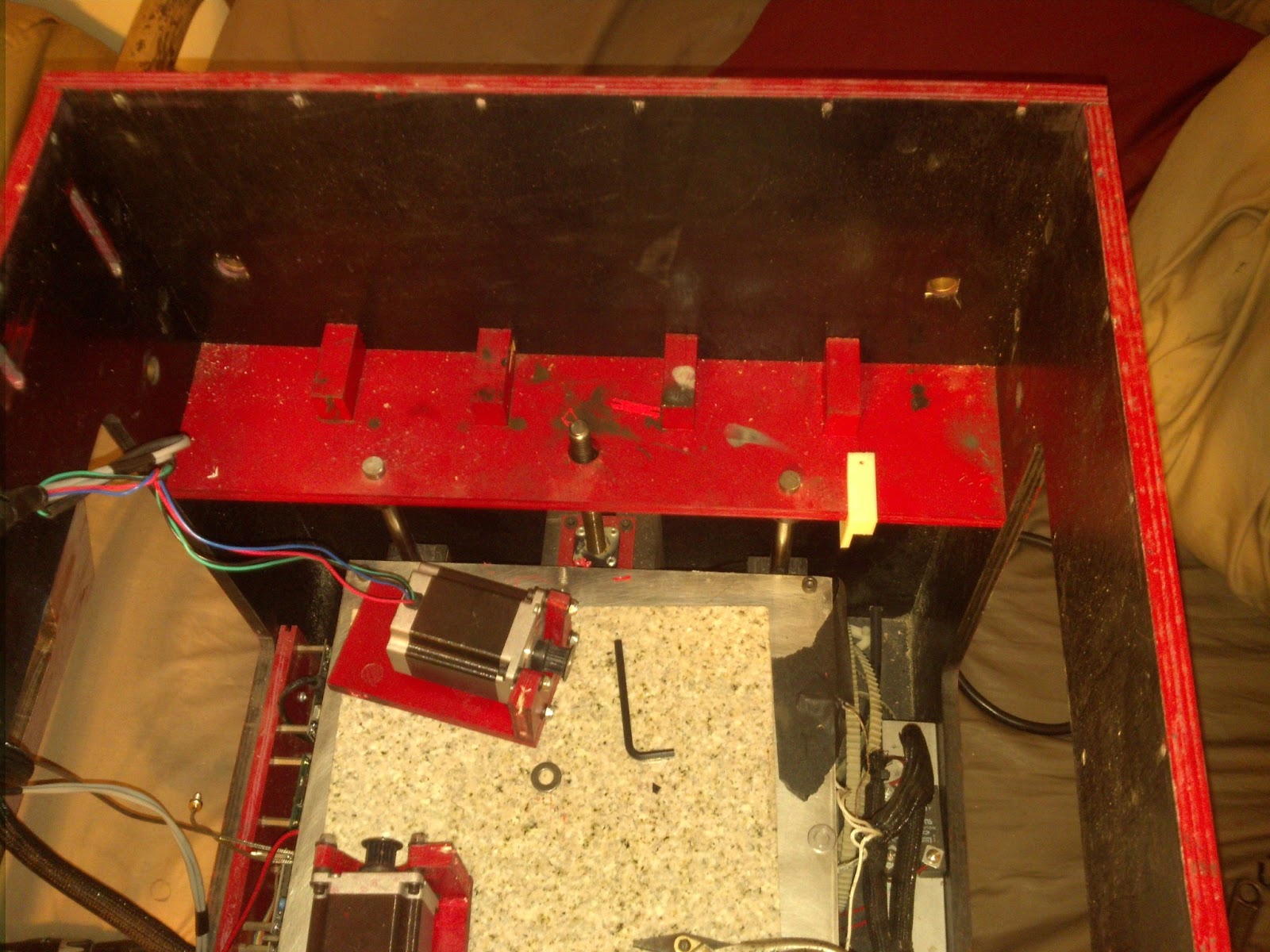
Now for a picture, the following picture is before the Z axis slide was installed and before the wires were tidied up.